Weider 9940 User Manual
Browse online or download User Manual for Sports and recreation Weider 9940. Weider 9940 User Manual
- Page / 33
- Table of contents
- BOOKMARKS
Summary of Contents
®USER’S MANUALModel No. WESY97310Serial No. The serial number is found in thelocation shown below. Write theserial number in the space above.SerialNum
1515. Attach each of the four Weight Guides (15) to theWeight Top Frame (66) with a 3/8” x 3 3/4” Bolt (59),a 3/8” Flat Washer (48), and a 3/8” Nylon
1120. Locate and open the parts bag labeled “PULLEYBAG 2.” Remove one “V”-Pulley (27) from thebag. Leave the remaining pulleys in the bag foridentifi
1223. Attach the Butterfly Cable (73) to the bracket on theRight Butterfly Arm (11) with a 3/8” x 1” Bolt (84) andtwo 3/8” Nylon Jamnuts (63). Note: T
1326. Wrap the Ab Cable (74) around a 3 1/2” Pulley (24) inthe direction shown. Attach the Pulley to the SmallPulley Bracket (22) with a 3/8” x 1 3/4”
1429. Wrap the Ab Cable (74) around a 4 1/2” Pulley (82) inthe direction shown. Attach the Pulley inside the indi-cated bracket on the Weight Top Fram
1531. Remove a Pro Pulley (26) from the bag labeled“PULLEY BAG 2.Identify the Low Pulley Cable (75). It is approximately143 1/2” long and it has a bal
1635754648486335. Attach the loop on the end of the Low Pulley Cable(75) to the indicated hole in the Small Leg Lever (41)with a 3/8” x 2 3/4” Bolt (4
1739. Important: Although the following steps are notdifficult to perform, the correct routing of thecable is critical to the functioning of the homeg
1843. Wrap the Press Cable (72) around a 3 1/2” Pulley(24) in the direction shown. Attach the Pulley and aCable Trap (25) to the indicated hole on the
1947. Route the threaded end of the Press Cable (72)around the 3 1/2” Pulley (24) that was mounted on thebracket on the Weight Base (5) in an earlier
2Important Precautions . . . . . . . . . . . . . . . . . . . . . . . . . . . . . . . . . . . . . . . . . . . . . . . . . . . . . . . . . . . . . . .
20Seat Assembly50. Locate and open the parts bag labeled “SEATASSEMBLY.”Attach the Backrest (12) to the indicated holes in theButterfly Upright (1) wi
21Miscellaneous Assembly52. Insert a 1/4” x 2 1/2” Carriage Bolt (45) through thecenter hole in a Seat Plate (65). Attach the Seat Plateto a Seat (13)
225656. Apply the WEIDER PRO 9940 decal in the location shown. Important: The warning decals shown belowhave been attached to the home gym in the loca
23Cable DiagramsThe cable diagrams below and on the next page show the proper routing of the Butterfly Cable (73), the AbCable (74), the Low Pulley Ca
24142151513693711481012Press Cable (72)
25ADJUSTING THE LEG PRESS PLATETo adjust the position of the Leg Press Plate (55), pull outthe Lock Pin (91) and slide the Adjustment Tube (90)backwar
26Slack can be removed form the Press Cable (72) bymoving one or both of the “V”-Pulleys (27) on the PressCable. One “V”-Pulley (27) is attached to th
27The threaded ends on the Press Cable (72) and the AbCable (74) that are attached to the weight stacks can alsobe used to tighten the cables. To tigh
3/8" Nylon Locknut (50)3/8" Nylon Jamnut (63)5/16" Nylon Locknut (64)1” Tap Screw (80)3/8" x 2" Bolt (54)1/4" Flat Washe
3/8" x 3 1/2" Bolt (56)3/8" x 4 3/4" Bolt (60)3/8" x 2 3/4" Bolt (46)3/8" x 3" Bolt (88)3/8" x 3 1/2"
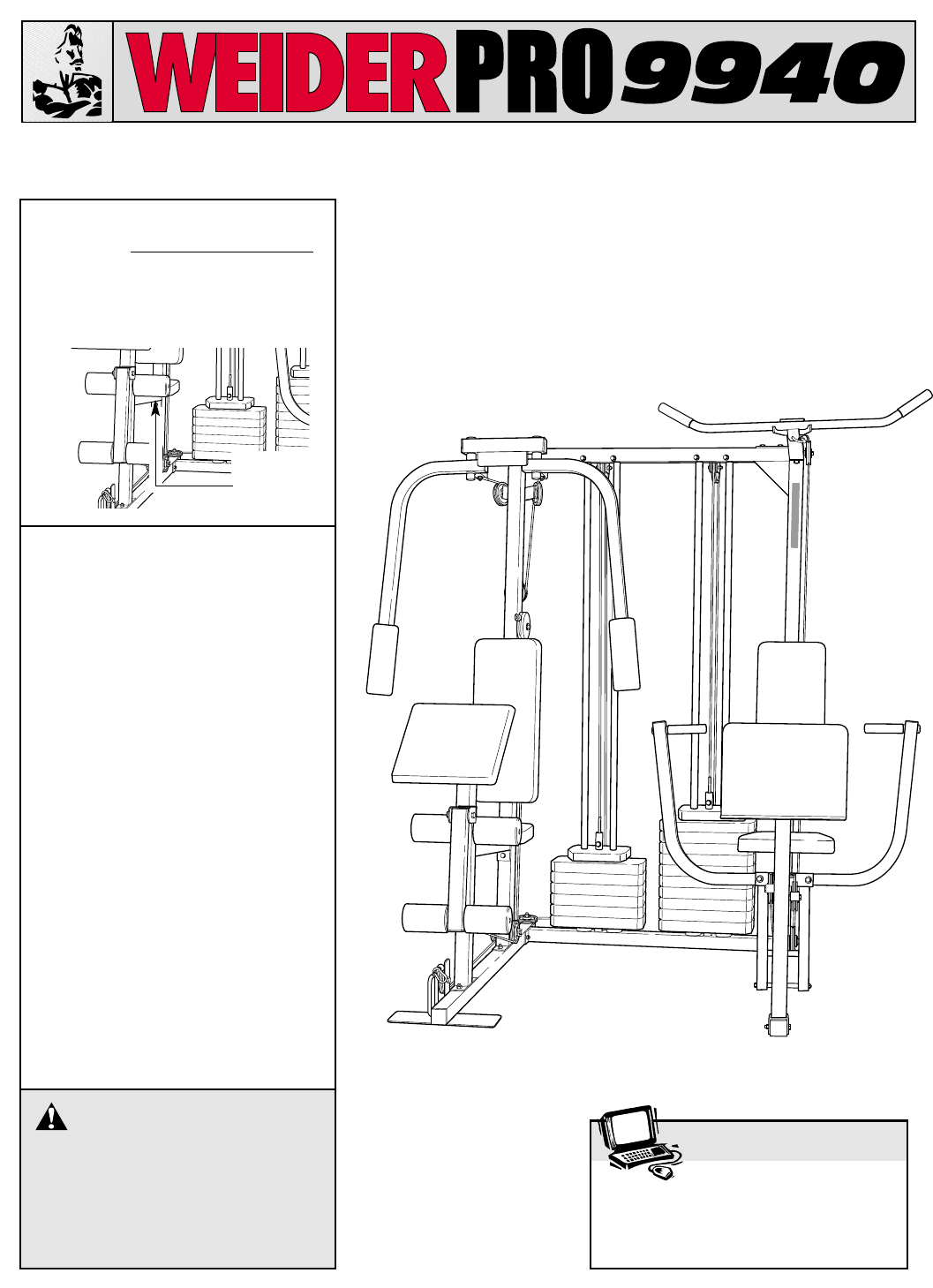
3ASSEMBLED DIMENSIONS: Height: 77 in.Width: 80 in. Depth: 55 in. Low PulleyStationFoot PlateLegLeverPress ArmsBackrestCurl PadButterflyArmsAb PulleySt
3/4" Round Inner Cap (43)1” Retainer Ring (31)1" Round Outer Cap (38)1" Square Inner Cap (98)1 3/4" Square Inner Cap (35)1" R
Note: “#” indicates a non-illustrated part. Specifications are subject to change without notice. Part List—Model No. WESY97310 R0601AKey No. Qty.
465757595924502446785660598762525087646425632489929295646430304351898025245462635024255088246063252492921011028987647179685024572257502467588169502447
ORDERING REPLACEMENT PARTSTo order replacement parts, simply call our Customer Service Department toll-free at 1-800-999-3756, Mondaythrough Friday, 6
4Note: This introduction will save you more timethan it takes to read it!Identifying PartsTo help you identify the small parts used in assem-bly, we h
1. Before beginning, make sure that you have readand understood the information on page 4.Locate and open the parts bag labeled “FRAMEASSEMBLY.”See dr
3. Place the bracket on the lower end of the ButterflyUpright (1) over the indicated 5/16” x 2 1/2” CarriageBolts (92) in the Butterfly Base (4). Hand
7. Press a 1” Square Inner Cap (98) into the small tubeon the Press Upright (2).Place the bracket on the lower end of the PressUpright (2) over the i
810. Lubricate the 3/8” x 3” Bolt (88). Attach the Leg PressLever (83) to the Press Base (6) with the Bolt and a3/8” Nylon Locknut (50). Do not overti
914. Attach the Weight Top Frame (66) to the Press TopFrame (9) with one 3/8” x 2 3/4” Bolt (46), a SupportPlate with 4” center holes (94), and a 3/8”
Related products and manuals for Sports and recreation Weider 9940
 (27 pages)
© 2020, manymanuals.com. All rights reserved. | 0.096 s |
 Manymanuals.com
 Manymanuals.de
 Manymanuals.fr
 Manymanuals.it
 Manymanuals.pl
 Manymanuals.cz
 Manymanuals.es
 Manymanuals-pt.com
Comments to this Manuals