Weider WEEVSY8721 User Manual
Browse online or download User Manual for Fitness, gymnastics & weight training Weider WEEVSY8721. Weider WEEVSY8721 User's Manual
- Page / 30
- Table of contents
- BOOKMARKS
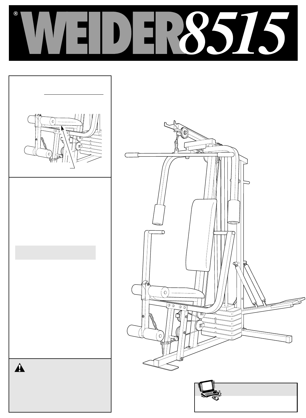
- USER'S MANUAL 1
- TABLE OF CONTENTS 2
- IMPORTANT PRECAUTIONS 2
- WARNING: 2
- BEFORE YOU BEGIN 4
- ASSEMBLY 5
- FRAME ASSEMBLY 6
- FRAME ASSEMBLYARM ASSEMBLY 8
- ARM ASSEMBLY 9
- CABLE ASSEMBLY 10
- SEAT ASSEMBLY 14
- HOW TO USE THE WEIGHT SYSTEM 17
- CABLE DIAGRAM 22
- 08457 089 009 24
- ORDERING REPLACEMENT PARTS 24
- CHART FROM THE MANUAL 25
- DRAWING FROM THE MANUAL 28
Summary of Contents
USER'S MANUALQUESTIONS?As a manufacturer, we are com-mitted to providing completecustomer satisfaction. If youhave questions, or if there aremiss
10CABLE ASSEMBLYAs you assemble the cables and pulleys insteps 14 through 22, please refer to theCABLE DIAGRAM on page 22 of this manual.14. Route the
CABLE ASSEMBLY171550202157152366648716236816. Route the Long Cable (23) around the “V”-Pulley (6) on the Right Arm (48). Be sure thatthe Cable is in t
18. Route the Long Cable (23) around the 3 1/2”Pulley (15) attached to the bracket on the TopFrame (55). Tighten the 3/8” x 2” Bolt (12)and the 3/8” N
CABLE ASSEMBLY12369581521669291720212210586710575820. Route the Short Cable (58) around the 3 1/2”Pulley (15) attached to the upper hole in thePress F
14CABLE ASSEMBLY22. Attach the Long Cable (23) to the Small “U”-Bracket (67) with a 1/4” Nylon Locknut (2)and a 1/4” Washer (10). Do not completelytig
1525. Press a 1 1/2” Square Inner Cap (32) into theLeg Lever (29).Lubricate the 5/16” x 2 1/4” Bolt (33). Attachthe Leg Lever (29) to the Seat Frame (
1628. Make sure that all parts have been properly tightened. The use of the remaining parts will be explained inHOW TO USE THE WEIGHT SYSTEM, beginnin
17HOW TO USE THE WEIGHT SYSTEMThe instructions below describe how each part of the weight system can be adjusted. IMPORTANT: Whenattaching the lat bar
18ATTACHING AND REMOVING THE SEATSet the bracket on the Seat Frame (36) onto the indi-cated pins on the Front Upright (42). Attach the SeatFrame to th
LOCKING THE WEIGHT STACKWhen the weight system is not in use, the Lock Pin(90) and Lock (91) should be attached. Insert theLock Pin through a Weight G
2TABLE OF CONTENTSIMPORTANT PRECAUTIONS . . . . . . . . . . . . . . . . . . . . . . . . . . . . . . . . . . . . . . . . . . . . . . . . . . . . . . .
20WEIGHT PRESS ARM BUTTERFLY ARM LEG LEVER HIGH PULLEY LOW PULLEYPLATES (lbs.) (lbs.) (lbs.) (lbs.) (lbs.)Top 20 10 15 14 24145 22 36 28 54270 33 54 4
21TROUBLESHOOTING AND MAINTENANCE Inspect and tighten all parts often and replace any worn parts immediately. The weight system can be cleanedusing a
22432765432Weight Stack—81—Low Pulley1—High PulleyLong Cable (23)5—Long “U”-BracketShort Cable (58)TOP VIEWCABLE DIAGRAMThe cable diagram below shows
NOTES23
ORDERING REPLACEMENT PARTSIf you encounter any difficulties or problems with this product, contact the ICON Fitness Lifestyle Ltd. office, orwrite: IC
IMPORTANT: Assembly is divided into four stages: 1) frame assembly, 2)arm assembly, 3) cable assembly, and 4) seat assembly. The hardwarefor each stag
1" Round Inner Cap (49)1" Round Cover Cap (70)3/4" Round Inner Cap (34)1/2" x 3/4" Spacer (61)1 1/2" Square Inner Cap (3
5/16"Nylon Locknut (3)1/4" Washer (10)5/16" Washer (8)1" Retainer (69)1/4" x 2 1/2" Screw (43)5/16" x 1 3/4" B
81REMOVE THIS PART LIST/EXPLODEDDRAWING FROM THE MANUALSAVE THIS PART LIST/EXPLODED DRAWING FOR FUTURE REFERENCE
Note: “#” indicates a non-illustrated part. Specifications are subject to change without notice. See the back coverfor information about ordering repl
The decals shown below have been placed on the weight system in the locations shown. If decals aremissing or illegible, please call our Customer Servi
231111885527121544157123214421361603355114192651256463376729923341276541104332165074275062169706970474844454445525339496221067543131741268553216615207
4BEFORE YOU BEGINASSEMBLED DIMENSIONS: Height: 188 cm (74 in.)Width: 102 cm (40 in.) Length: 135 cm (53 in.) Foot PlateLow Pulley StationHigh Pulley S
5ASSEMBLY156High Side ofBracketHandles3551Long Side31511411274Before beginning assembly, carefully read thefollowing information and instructions:• Pl
6FRAME ASSEMBLY2. Slide the Front Upright (42) onto the 5/16” x2 1/2” Carriage Bolts (1) in the Base (4).Hand tighten a 5/16” Nylon Locknut (3) ontoea
5. Lubricate the pedal axles on the Rear Upright(56). Slide the Left Pedal (79) onto the leftpedal axle, and the Right Pedal (78) onto theright pedal
8FRAME ASSEMBLYARM ASSEMBLY9. Press the Weight Tube Bumper (64) into theend of the Weight Tube (63). Insert theWeight Tube into the stack of Weights (
9ARM ASSEMBLY12. Wet the handle of one Press Arm (46) withsoapy water. Slide a 5” Plastic Grip (31) ontothe handle. Press a 1” Round Inner Cap (49)int
Related products and manuals for Fitness, gymnastics & weight training Weider WEEVSY8721
 (20 pages)
© 2020, manymanuals.com. All rights reserved. | 0.096 s |
 Manymanuals.com
 Manymanuals.de
 Manymanuals.fr
 Manymanuals.it
 Manymanuals.pl
 Manymanuals.cz
 Manymanuals.es
 Manymanuals-pt.com
Comments to this Manuals